
OverView
Stepping motors can be viewed as electric motors without commutators. Typically, all windings in the motor are part of the stator, and the rotor is either a permanent magnet or, in the case of variable reluctance motors, a toothed block of some magnetically soft material. All of the commutation must be handled externally by the motor controller, and typically, the motors and controllers are designed so that the motor may be held in any fixed position as well as being rotated one way or the other. Most steppers, as they are also known, can be stepped at audio frequencies, allowing them to spin quite quickly, and with an appropriate controller, they may be started and stopped "on a dime" at controlled orientations.
For some applications, there is a choice between using servomotors and stepping motors. Both types of motors offer similar opportunities for precise positioning, but they differ in a number of ways. Servomotors require analog feedback control systems of some type. Typically, this involves a potentiometer to provide feedback about the rotor position, and some mix of circuitry to drive a current through the motor inversely proportional to the difference between the desired position and the current position.
READ MORE………
OverView
Stepping motors can be viewed as electric motors without commutators. Typically, all windings in the motor are part of the stator, and the rotor is either a permanent magnet or, in the case of variable reluctance motors, a toothed block of some magnetically soft material. All of the commutation must be handled externally by the motor controller, and typically, the motors and controllers are designed so that the motor may be held in any fixed position as well as being rotated one way or the other. Most steppers, as they are also known, can be stepped at audio frequencies, allowing them to spin quite quickly, and with an appropriate controller, they may be started and stopped "on a dime" at controlled orientations.
For some applications, there is a choice between using servomotors and stepping motors. Both types of motors offer similar opportunities for precise positioning, but they differ in a number of ways. Servomotors require analog feedback control systems of some type. Typically, this involves a potentiometer to provide feedback about the rotor position, and some mix of circuitry to drive a current through the motor inversely proportional to the difference between the desired position and the current position.
In making a choice between steppers and servos, a number of issues must be considered; which of these will matter depends on the application. For example, the repeatability of positioning done with a stepping motor depends on the geometry of the motor rotor, while the repeatability of positioning done with a servomotor generally depends on the stability of the potentiometer and other analog components in the feedback circuit.
Stepping motors can be used in simple open-loop control systems; these are generally adequate for systems that operate at low accelerations with static loads, but closed loop control may be essential for high accelerations, particularly if they involve variable loads. If a stepper in an open-loop control system is overtorqued, all knowledge of rotor position is lost and the system must be reinitialized; servomotors are not subject to this problem.
Stepping motors are known in German as Schrittmotoren, in French as moteurs pas à pas, and in Spanish as motor paso paso.
Principle of a Stepper motor
The physical operation of a stepper motor is performed by magnetism – yes, magnets! So here are some basics to do with magnetism:
1. Magnets have two poles – just like the earth – called North and South
2. ‘Opposite poles attract’ – ie the North of one magnet will create a physical attraction (pull) for the South pole of another magnet. And vice-versa.
3. ‘Similar poles repulse’ – ie the North poles of two magnets will create a physical repulsion (push) for the North pole of another magnet. The same goes applies for South and South.
4. Some magnets are ‘permanent’ – ie they are always magnets with North and South being in the same place. Remember those horseshoe shaped magnets you had as a child or used at school to mess around with iron filings?
5. Take a metal bar and wrap some wire around it. Putting current through the wire will turn the bar into a magnet. This is called an electro-magnet. Depending on which direction the current is moving through the wire will decide which end of the bar is North and which is South.
So lets create a simplistic model of a stepper motor (NB this is very simplistic so don’t try it – it may not work in practice – its just a theoretical example!).
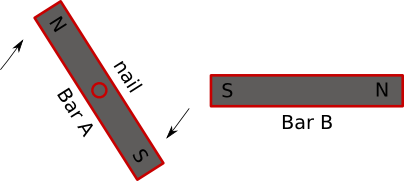
1-Lets take a bar magnet (ie a metal bar that is a permanent magnet with one end always being North and the other always being South). Lets call this ‘Bar A’.
2-Now take a non-magnetised metal bar, wrap some wire around it to create an electro-magnet and call it ‘Bar B’.
3-Lets bang a nail through the middle of Bar A so that it can spin – ie it drives the wheel of our robot
4-Lets superglue Bar B to our work surface with one end of the bar pointing at the nail in Bar A.
So now we have something like this:-

So now we turn on the supply across Bar B so a current runs through it and it becomes a magnet. Lets assume that the left end of Bar B becomes South. So now we have:-

So now we have two South poles facing each other and we know that ‘similar poles repulse’. Bar B is super glued to the table so only Bar A can move – and that has a nail in it so it can only spin. So Bar A starts to spin. Whilst the South pole of Bar A spins away from Bar B then this ‘repulsion’ becomes less. But wait a moment – this means that North pole of Bar A gets closer to the South pole of Bar B and we know that opposite poles ‘attract’. So this will ‘pull’ the North pole of Bar A towards the South pole of Bar B
Until, eventually, Bar A has spun a complete 180 degrees.

At this point: Bar A will stop spinning because its North is ‘pulled’ by the South pole of Bar B.
We have just made one ‘step’ – but, now what! Well, we reverse the voltage in the wire around Bar B so that the magnetism of its poles get ‘flipped’ – so we now have:-

So now we have two North poles facing each other and we know that ‘similar poles repulse’ So, just like before, Bar A will do another spin through 180 degrees until, after our second ‘step’, we get:-

Reverse the current in Bar B, and hence the polarity, and we are back to where we started:-
and so we keep on going.
Hey we have a motor ! Even though it is super glued and nailed to our dinning room table!
So how do we control the speed of the motor and what limits the maximum?
In our simplistic example, then the quicker we change the polarity of Bar B then the quicker the motor (Bar A) will turn. However, in practice, this is not the case since the switch in current on Bar B has to co-inside with the position of Bar A so that the necessary ‘push’/’pull’ is applied at the correct time. Hence this depends on how fast Bar A can rotate and, since this is a physical movement, it does take a minimum finite amount of time. So assuming that we have:
and Bar A starts spinning (because South repels South). But then we change the polarity of Bar B almost immediately. Then Bar A is attracted back to where it came from and so the result is ‘No Movement’ even though you have sent ‘2 steps’. This physical movement duration therefore dictates the maximum frequency at which you can issue new step commands. A typical motor frequency may be 400Hz – ie you can do a maximum of 400 steps per second.
So what have we learned? We have a basic understanding of how stepper motors work and we have created a motor that turns 180 degrees for each step – so 2 steps make Bar A spin though a complete 360 degrees. We have also learned that a motor has a maximum number of steps per second.
Actual Working of a Stepper motor
So lets now leave our imaginary world and look at how this extends to real stepper motors.
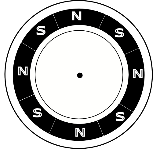
Our rotating ‘Bar A’ only had two poles – one at each end of the bar – and so we only got two steps per revolution. A real stepper motor may have, for example, 48 steps per revolution and each step would therefore move through 360/48 or 7.5 degrees per step. How does this happen? Well, rather than it being a bar, then think of it as a cylinder where every 7.5 degrees the polarity is either North or South but it always alternates from one to the other. That’s why stepper motors always have an ‘even’ number of steps. Here’s what it may look like if we look down on it and there are only 8 steps:-
Now instead of one Bar B we actually have two. Each of these two electro-magnets will have a coil around them. To complicate things slightly there are two different ways that these coils are configured: bi-polar, and ‘uni-polar’.
We will look at Bi-Polar first because it is the simplest to understand whereas a Uni-Polar motor has other advantages and disadvantages but can, when required, be used as if it was a bi-polar motor.
Bi-polar stepper motor
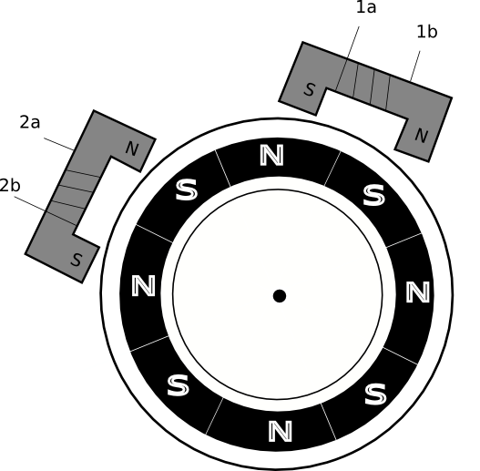
As you can see it has two coils and will normally therefore have 4 leads. If you have no documentation for your motor then you can just use an ohmmeter to work out each pair of pins. I.e. 1a and 1b will have a low resistance between them, and 2a and 2b will also have a low resistance. If you measure across two pins and have an infinite resistance then they are from different coils. So once you know which two pins are coil 1 and which are coil 2 then you will still need to find out which are ‘a’ and which are ‘b’ – but more on that later.
How to Drive
To drive the motor then let us consider one of the coils – say coil 1. In order to become an electromagnet we need to be able to change the direction of the current through the coil. So each side of the coil needs to be either or low.
If ‘1a’ is high and ‘1b’ is low then we will have a current through the coil.
If ‘1a’ is low and ‘1b’ is high then we will have a current through the coil in the opposite direction.
In the other two cases: where they are both high, or both low, then no current flows and so it is no longer a magnet.
A suitable circuit to do this as an H-Bridge. As you will see from that link – you need four switches in the H-Bridge to be able to give the four control states we have mentioned above.
Uni-polar stepper motor
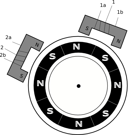
The only difference is that each of the coils now has 3 wires and will normally there have 6 leads. The new wire on each coil is called a ‘centre tap’ and is connected to the middle of the coil. If you have no documentation on your motor then use your ohmmeter to check the connections. By checking for infinite resistance then you should be able to identify the leads that are for one coil, and the other leads for the other coil. Given a group of 3 leads you can tell which is the centre tap because, for coil 1, the resistance between ‘1a’ and the centre tap will be same as that between the centre tap and ‘1b’. The resistance between ‘1a’ and ‘1b’ will be double this value. NB the resistance tend to be very low, a few ohms, so you will need to select the appropriate resistance scale on your meter.
How to Drive
As mentioned earlier: you can drive a uni-polar motor ‘as if’ it was a bi-ploar motor. To do this you just ignore the centre tap and then use the other two leads per coil as if it was a bi-polar.
Otherwise: you want to use the centre tap and, assuming you connect it to ground, then you will need two switches to dictate which direction the current flows through the coil.

Note that this mode of operation means that you are only using half of the coil in each direction. This will mean the ‘half coil’ only has half of the total resistance. Using Volts = Amps x Resistance (and assuming your supply voltage is the same) then if the resistance is halved then the current drain has doubled.
So why would you choose uni-polar over bi-polar if it requires twice as much current?
Compared to the bi-polar H-Bridge driver, which requires ‘4 switches; per coil then the uni-polar circuit only needs ‘2 switches’ per coil. So less electronics!
The price you pay is that you may be using twice as much current and because you are using half of the coil at a time then you may only get half the torque. Despite its name (uni versus bi) it sounds as if it is less capable but remember you can always use a uni-polar motor as if it was a bi-polar by ignoring the centre tap. So a uni-polar can be thought of as a bi-polar with extra choices.
Previous discussions have described the way to wire up bi-polar and uni-polar motors. These configurations effect current drain, torque but don’t change the way they are programmed.
As we have already mentioned – unlike a DC motor – you cannot just apply a fixed current and get to the motor to spin. Instead you need to supply pulses to the coils in a certain order. There are various ways to0 do this and each one has trade-offs to do with torque vs current consumption. So now we will look at the possibilities:-
The most simple ‘pulsing’ is called ‘Wave Drive’ and sets the coils as follows:-
|
|
T
|
T + 1
|
T +2
|
T + 3
|
|
1a
|
High
|
Low
|
Low
|
Low
|
|
1b
|
Low
|
Low
|
High
|
Low
|
|
2a
|
Low
|
High
|
Low
|
Low
|
|
2b
|
Low
|
Low
|
Low
|
High
|
This method only energises one coil at a time. So current consumptions is low. But equally the amount of torque is also low.
The next ‘pulsing’ method is called ‘Full Step Drive’
|
|
T
|
T + 1
|
T +2
|
T + 3
|
|
1a
|
High
|
High
|
Low
|
Low
|
|
1b
|
Low
|
Low
|
High
|
High
|
|
2a
|
Low
|
High
|
High
|
Low
|
|
2b
|
High
|
Low
|
Low
|
High
|
This method energises both coils at the same time- so requires twice the amount of current but provides about 40% more torque compared to Wave Drive. The other benefit of this method is that 1a is always the ‘inverse’ of 1b, and likewise 2a is always the ‘inverse’ of 2b. So we could control the motor with two output pins from the controller and, in our motor driver hardware, we could use an inverter between 1a-1b and another between 2a-2b.
The last pulsing method is called ‘Half Step Drive’ or ‘Micro-stepping’.
|
|
T
|
T+1
|
T+2
|
T+3
|
T+4
|
T+5
|
T+6
|
T+7
|
|
1a
|
High
|
Low
|
Low
|
Low
|
Low
|
Low
|
High
|
High
|
|
1b
|
Low
|
Low
|
High
|
High
|
High
|
Low
|
Low
|
Low
|
|
2a
|
High
|
High
|
High
|
Low
|
Low
|
Low
|
Low
|
Low
|
|
2b
|
Low
|
Low
|
Low
|
Low
|
High
|
High
|
High
|
Low
|
This method alternates between energising 2 coils and 1 coil. So the current requirements, and torque delivered, sit half way between ‘Wave Drive’ and ‘Full Step Drive’. It also helps to avoidance something called ‘resonance’ which can occur when using ‘Full Step Drive’ at certain speeds. The other side effect is to double the number of steps per revolution – which helps accuracy – but halves the overall maximum speed.
What have we learned? There are at least 3 ways to drive a stepper motor depending on whether we want o optimise torque or minimise current consumption. Since these do not require hardware changes then we could dynamically change from one drive mode to another in software depending on circumstances. For example: on a flat surface we might choose ‘Wave Drive’ and when a tilt switch in the robot tells us we are going up a steep hill the then we could change to ‘Full Step Drive’. Since the choice of drive method effects current then you also need to make sure that the current requirement does not exceed the ability of your batteries or of your H-Bridge output stage components.
We will discuss following methods in the Next Post
-
Computer Control
-
8051 Control
-
PIC Control
-
AVR Control
The mode used will be C in all the mediums and also in VB for use with Windows.
See You Soon